
 Nederlands
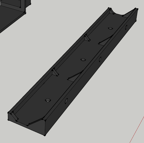
Blog / Drawings
Posted on 12 April 2013 at 10:08 pm (CET)
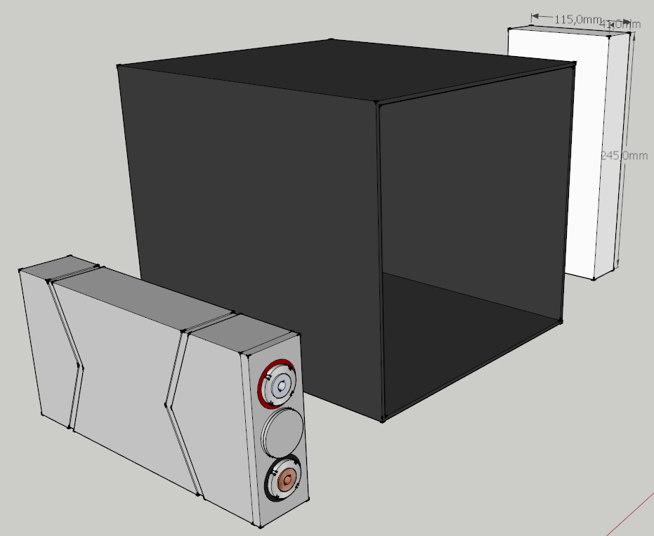
Here's what I had in mind to hold the batteries in place and it's also for attaching the cover. There will be rivet nuts in all of the holes and everything will be fastened from the outside this way.
Don't know if the triangular shapes are necessary but it should be sturdier that way.
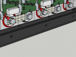
Here it's in the battery box.
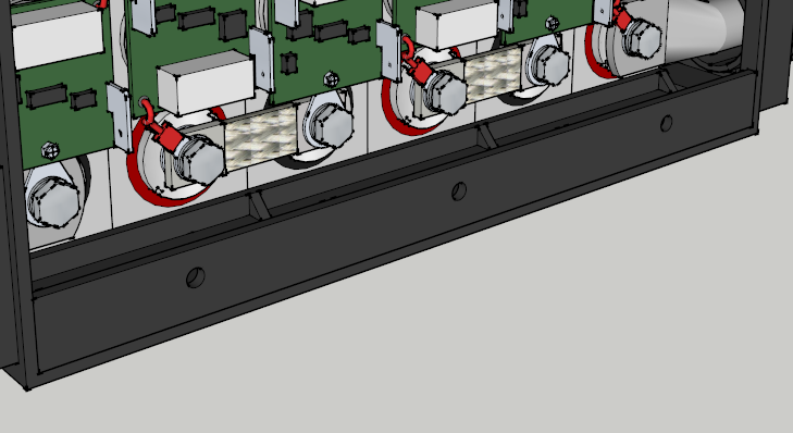
Might have to add something else in the middle of this battery box though since there are 2 rows of batteries in it. The other battery boxes will all have 1 row so it should be easier for those.
Posted on 11 April 2013 at 10:57 pm (CET)
I've continued with the 3D drawing.
I think the only way to secure the batteries is to place an L-profile of the same material as the battery box at the top and bottom and fasten them from the outside with bolts. I want to use rivet nuts with this and seal it with rubber to make it waterproof. No idea how else to do it.
I'm also not really sure yet if the batteries will actually be placed in this position, will have to wait till I receive the batteries. Only then I can see how they'll fit.
Was a bit bored today waiting for the plate for the motor mount to arrive. So I played around a bit in SketchUp and replicated the batteries I will be using. Think it turned out pretty well, first time actually using the program.
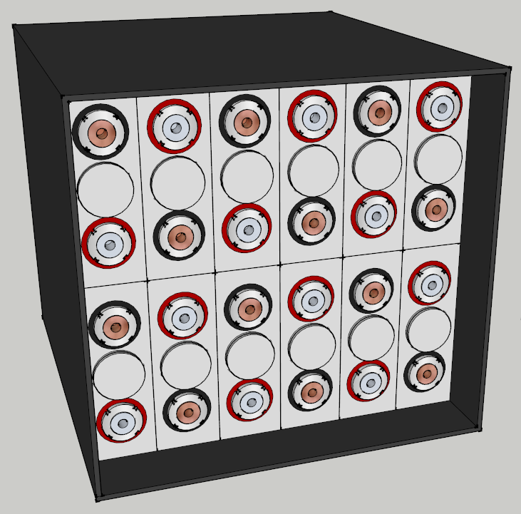
Also made one of the battery box (the biggest one) in which the batteries will be held together. And I'm in luck, there are 2 sizes given for the width of the batteries on the supplier's website but the smallest size seems to be correct. I always assumed the larger size to be correct. This will give me another 3mm to spare for each battery which is quite a lot really. Will be even easier to place them.
Only problem is I have to make sure they won't be able to move inside of the box. That's why I'm making this 3D drawing, to discover a solution for this.
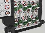
I also filled up the box with batteries, pretty fun program. Easy to work with.
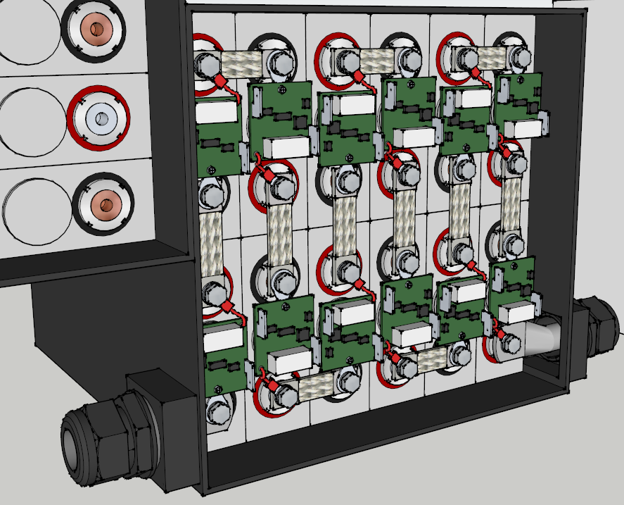
Think I'll continue and add the BMS boards and connections as well.
Posted on 25 March 2013 at 12:49 am (CET)
Category: Drawings, Electric motor
Posted on 25 March 2013 at 12:49 am (CET)
Category: Drawings, Electric motor
A while ago a friend of mine came by, he is in the metalworking business. Together we went looking for the best solution to mount the motor and if he could make a mount for it. He already had a few ideas but he would go and make a drawing of it first. Ended up being a few drawings since a few modifications had to be made.
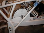
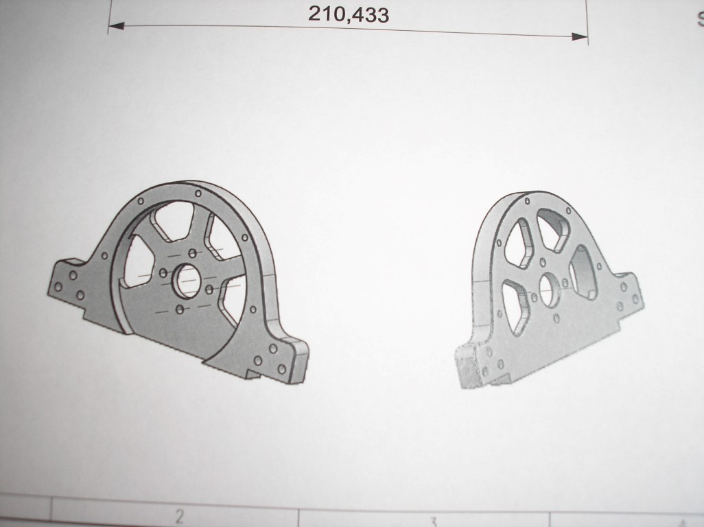
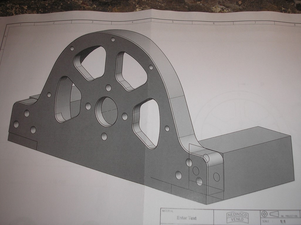
Meanwhile I received the final drawing and I'm checking if it can actually be fitted this way. First off, here's the drawing.
The 2 blocks that you can see will be welded on the rear swingarm.
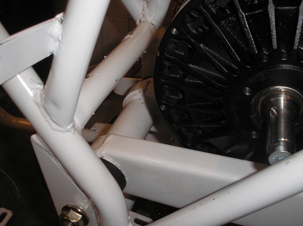
Here you can see where the motor will be placed. As you can see there is no need for modifications with the suspension, it fits perfectly in there.
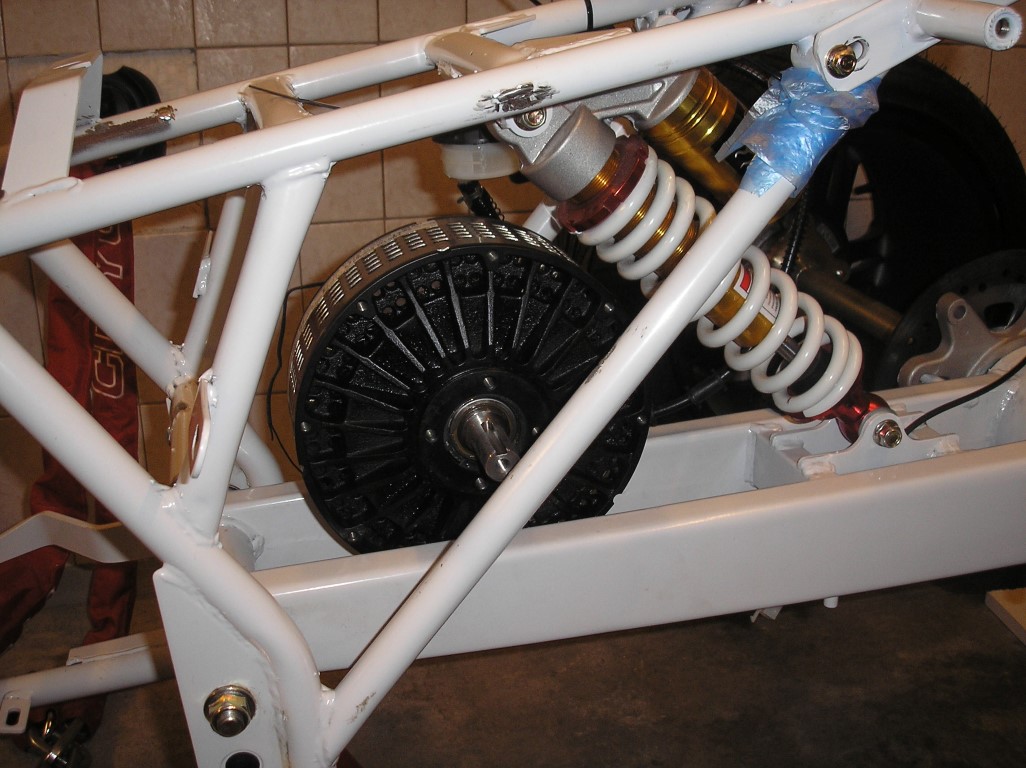
And I again made a paper model to see if the motor mount would fit. Still think it's the best way to measure.
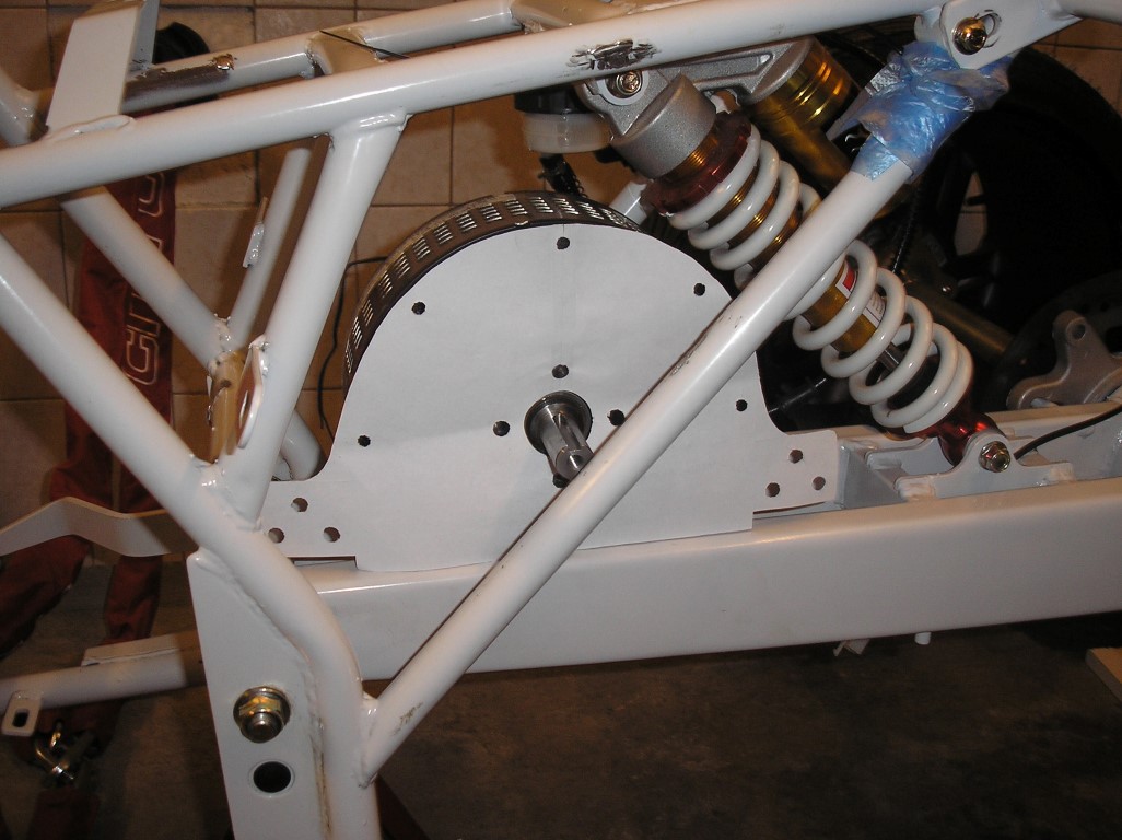
Only on the bottom left it will get a bit more sloped and only 2 mounting holes for mounting on the swingarm since the frame on the left side of the motor is in the way.
The motor mount can be made now. Will have to get the materials myself first, after that it would probably take around 2 weeks to make it. It'll probably become the best looking part on the quad bike.
Posted on 24 December 2012 at 06:13 pm (CET)
Posted on 24 December 2012 at 06:13 pm (CET)
Finished the whole wiring diagram now. Only still have to add the BMS but I can't yet till I actually have it here. No idea how it'll get wired up just yet.
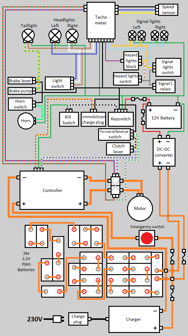
The only thing I'm not sure about is the clutch lever. I want to use this in combination with the forward/reverse switch to be able to drive in reverse. According to the regulations of the RDW (Dutch road safety institute) you need 2 seperate actions for this (or only able to activate below 5 kmh but this will be too complicated I think) so I think this will be the easiest solution. Just don't know if it's possible this way or if I'd be shorting out the controller when the switch is in reverse and the clutch lever isn't pulled. So I'll have to ask around a bit before I actually connect it like this.