Blog / Wiring (HV)
Posted on 7 October 2014 at 12:01 am (CET)
Category: Wiring (12V), Wiring (HV)
Posted on 7 October 2014 at 12:01 am (CET)
Category: Wiring (12V), Wiring (HV)
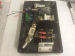
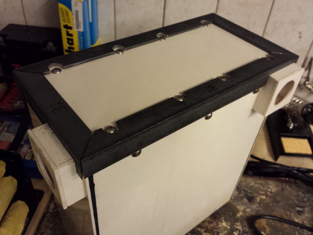
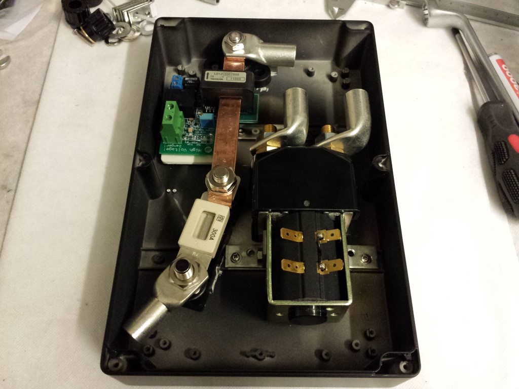
Tonight I finished the first box with high voltage parts. Had quite some work with this one since the standard mounting points weren't really useful and the box is also too low to make a plate for the bottom. Was also quite tricky to decide where to place everything, still is far from ideal but I can't really think of any better way.
In this are the main contactor (splits the battery pack in two to safely work on it and for emergencies), sensor plate for EV Display (gauge) and the main fuse. The orange cables I still have to connect, will do this once all of the boxes are done and placed in the frame. I did however connect the 12V part already, wasn't really much work for this box.
I also started with the last box already, this one's easier and will probably be finished tomorrow already. Meanwhile 15 of the 24 batteries are also charged already. So this weekend I hope to have them all charged. Then I can finally start placing them in the boxes and in the frame.
Posted on 13 June 2014 at 01:06 am (CET)
Posted on 13 June 2014 at 01:06 am (CET)
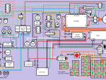
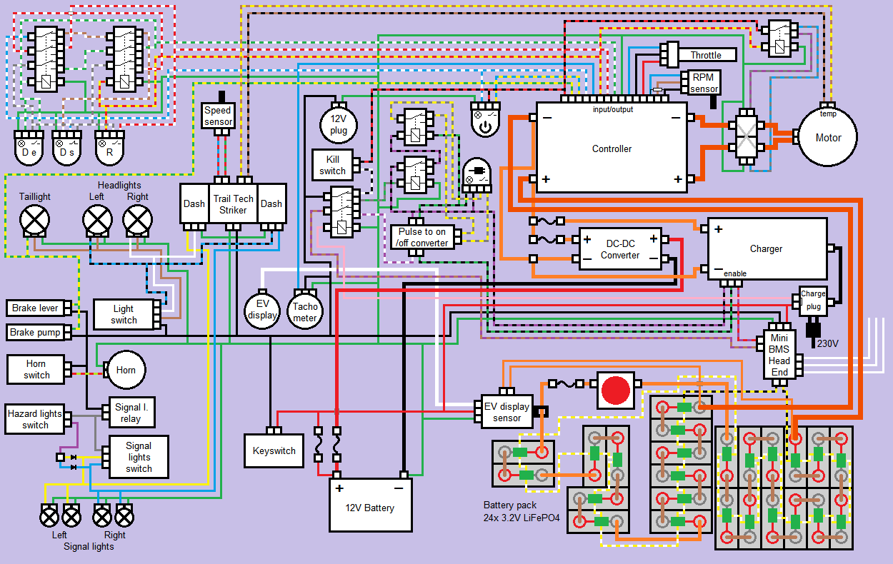
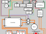
Past few days I've been busy drawing the whole wiring diagram. I'm pretty sure everything will actually be connected like this now. Only those 3 wires of the Battery Management System I'm not really sure about how to connect them yet. These are for drastically reducing the power when the batteries are empty so you can't undercharge them. But there should still be enough power to get the quad bike off the road safely. This can be connected in a few ways so I'll still wait with this.
Also made 2 extra circuits in it with a few buttons and relays. The one on the top left is for switching between low power (Drive Eco), high power (Drive Sport) and Reverse. And the one in the middle is for starting and stopping the charge process when the charge plug is connected. I might still get an actuator for this so the charge plug will get locked with this circuit while charging.
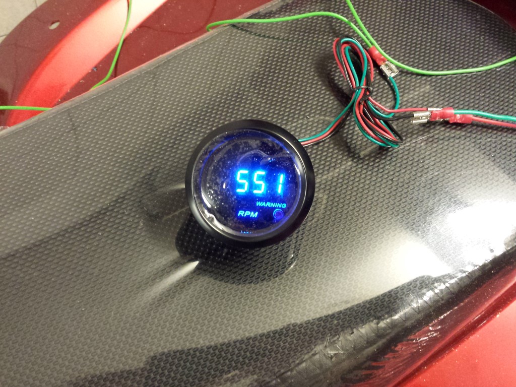
Also have another new tachometer, this time one from Hong Kong for 10 euros. And third time's the charm, this one works perfectly.
For the rest I've still been busy with the corner profiles on the side of the covers. Have to make quite a lot of cutouts in them for the cable glands and bolts. So this'll still take me a while. But for this battery box they're all done, still 3 to go.
Posted on 1 February 2013 at 10:30 pm (CET)
Posted on 1 February 2013 at 10:30 pm (CET)
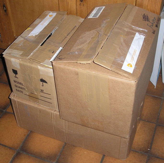
When I came home today I suddenly saw 3 packages, total weight of 40kg. What could be in there?
Finally the first few parts for the conversion have arrived. Thank you Rebbl!
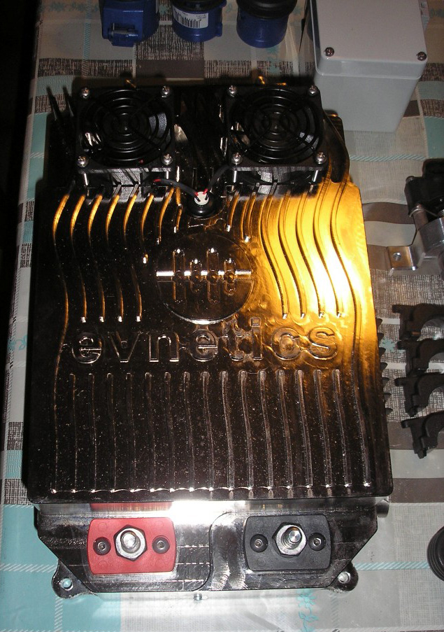
Most important part, the Evnetics Soliton Jr controller. Way overkill for this project but it's the only one that has the needed certification to pass inspection at the RDW. But it's the best you can get anyway, very high quality, a lot of options and not to mention it looks amazing.
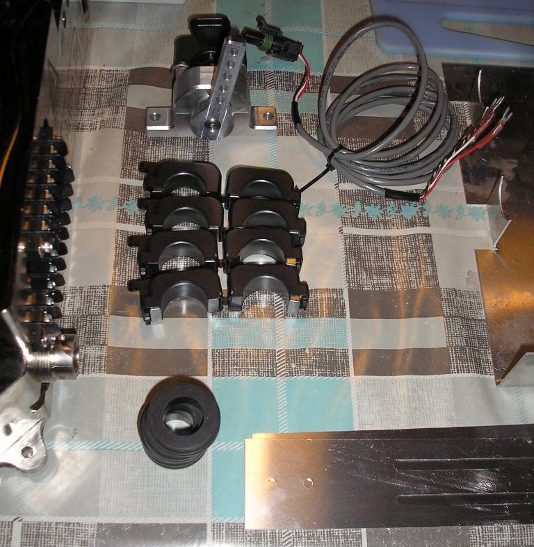
Next, on top is the hall sensor, also from Evnetics so very high quality as well. The 'gas' cable gets connected to this and it will send 0-5V to the controller. Below that are 4 RFI filters and rubbers to safely guide the cables through the enclosure for the controller.
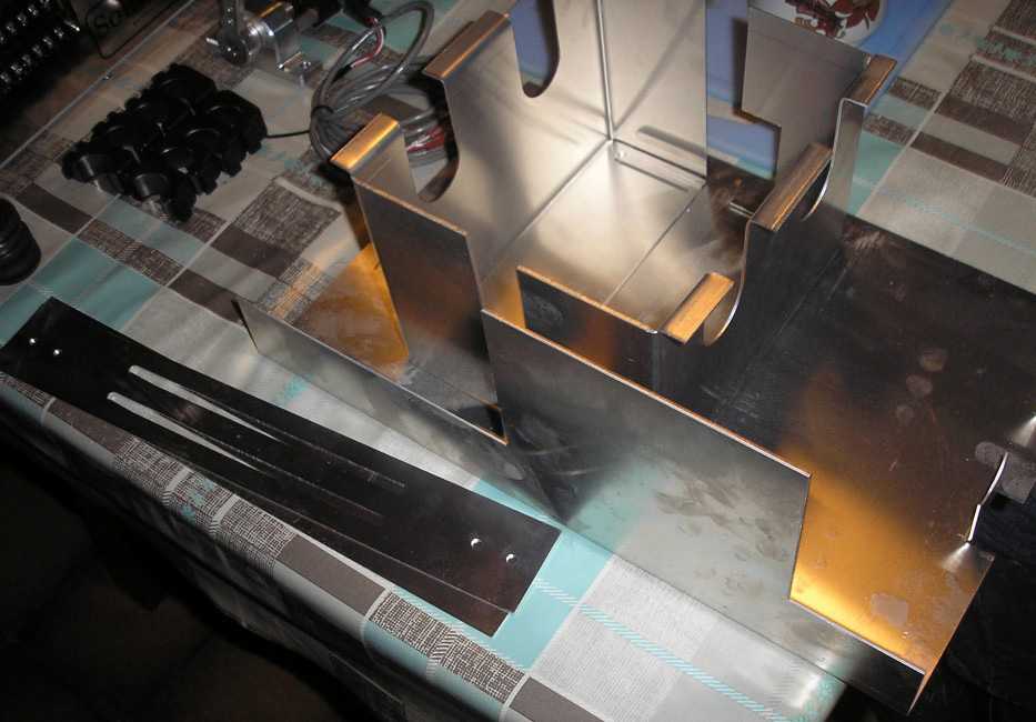
Enclosure for the controller, this consists of a few parts. This enclosure and the RFI filters (also a seperate mesh shielding that's already inside of the cables) are unfortunately necessary for the controller and motor to pass inspection at the RDW. All because of EMI (electromagnetic interference). The controller won't really be visible anymore which is a shame. But there's no other way, the rules are like this everywhere in Europe.
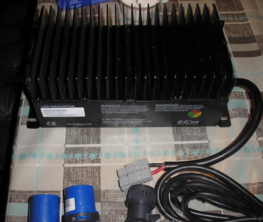
Also important, the charger to charge the batteries. This is already preprogrammed for the LiFePo4 batteries. I only gave them the info of the CALB SE70's so I hope the settings are still right for the CALB CA60's as well. Still have to ask for this.
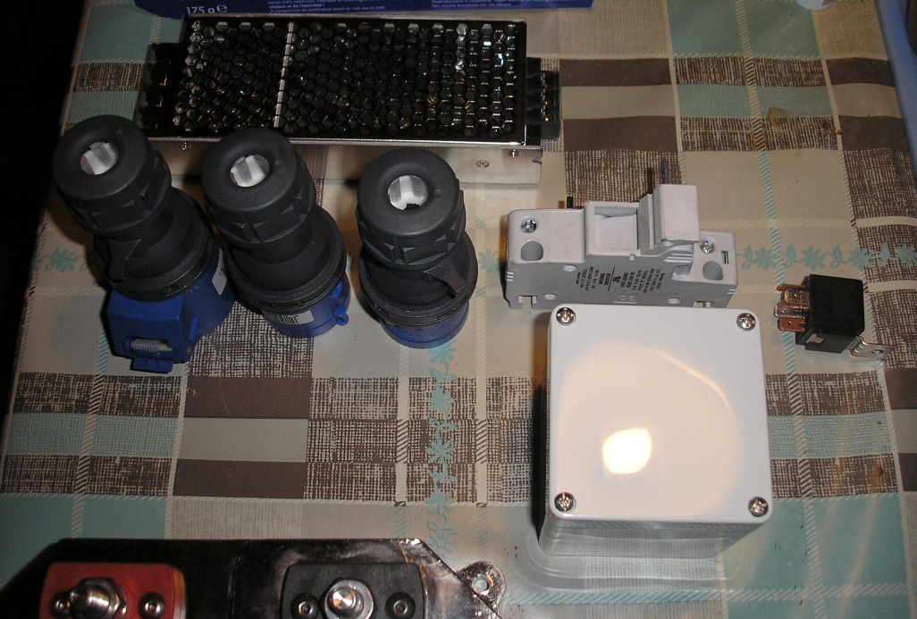
On top a 150W DC-DC converter. With electric vehicles this is used instead of a dynamo. This converts the 72V I'll be using for the propulsion to 12V to keep the 12V battery charged.
Also some plugs for charging, a fuse for the charger and a relais. I just don't know what the relais is for, as far as I know this isn't needed. But it'll be of good use anyway.
There's also a box which I think is meant for the fuse but it doesn't even fit. Will have to see what to do with this later, it's a pretty weird fuse anyway (can only see the fuse holder, fuse is inside of it). Usually other type of fuses are used for this.
Then there's still some cables.
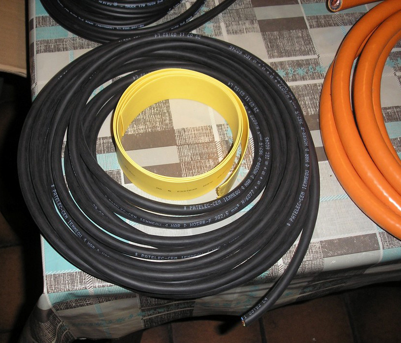
This one is to be used as the charge cable I guess. Will still have to ask for some more information on this as I don't think it's all complete for making the charge cable. The yellow roll is heat shrink.
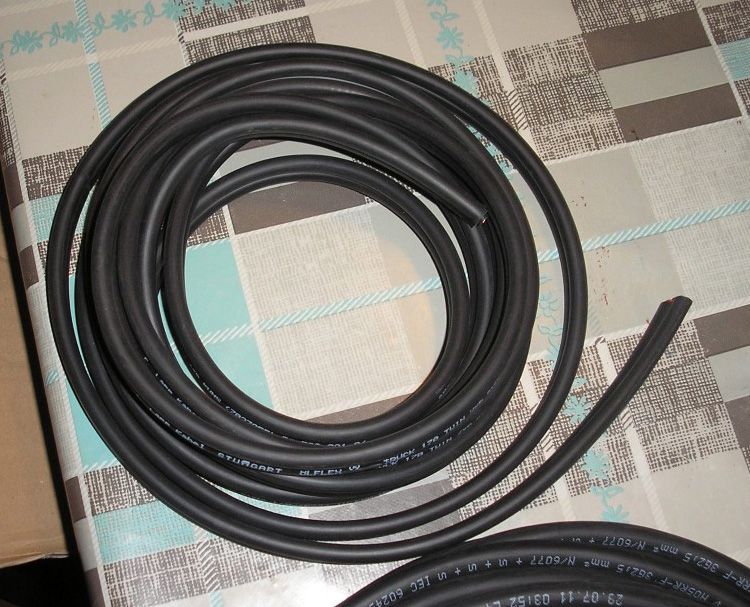
Cable for between the charger and batteries. Pretty nice they're tied together, easier to attach.
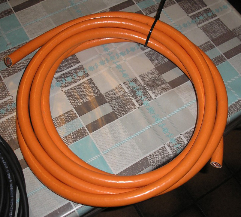
Orange cable for between the battery pack and the controller and between the controller and motor (with mesh shielding).
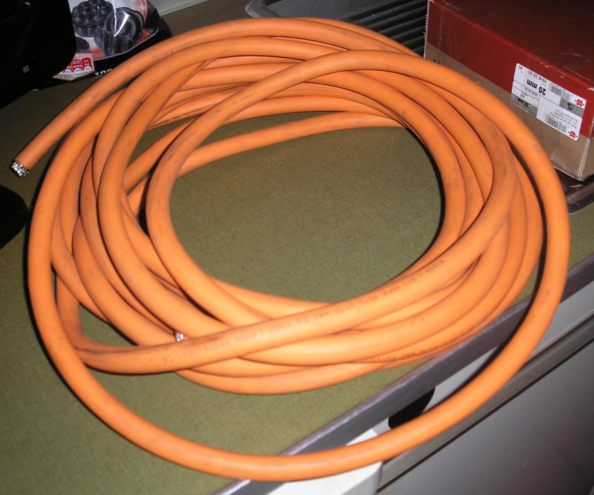
Orange cable for between the battery packs (without mesh shielding).
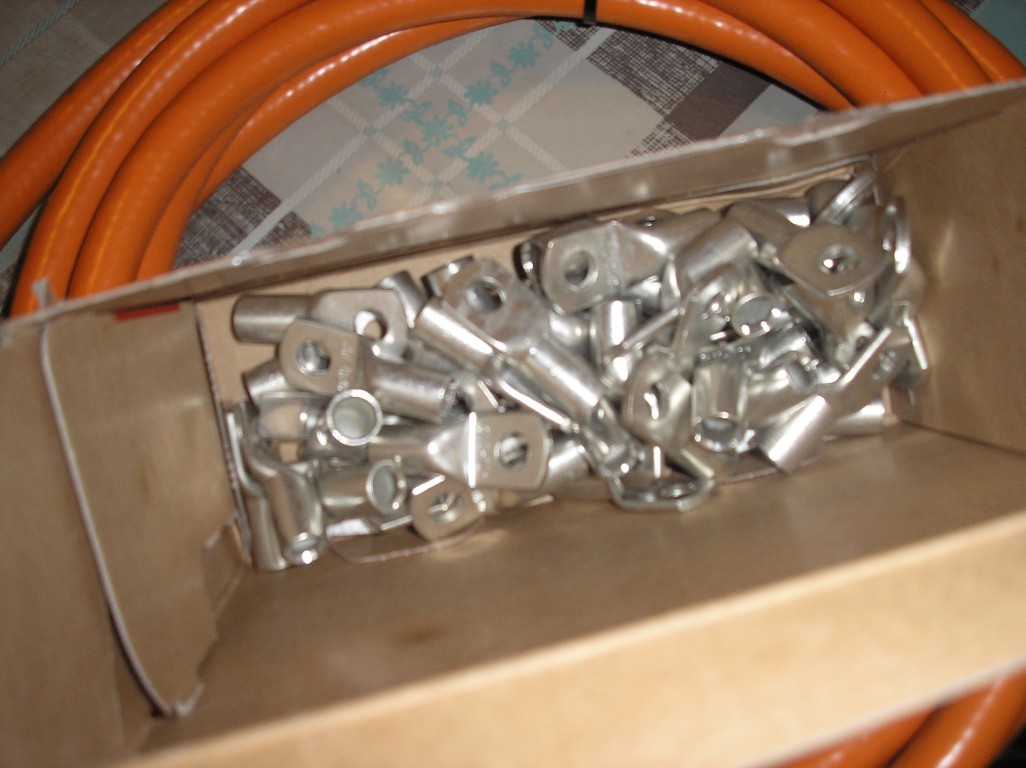
And last but not least cable shoes for the orange cables.
This isn't all the parts yet though, still need to get the following from different companies:
- Electric motor (within 2-3 weeks hopefully)
- Contactors (big relais) for forward/reverse (within 2-3 weeks hopefully)
- Emergency switch (within 2-3 weeks hopefully)
- Batteries (still have to order them, delivery time of 2 months)
- A few fuses (still have to order them)
But I did already get a lot of parts now, however I need to get some mounts made for the controller and motor. Only after that I can actually start with the wiring and other things. But I can actually do some things now while waiting for the motor to arrive.
Posted on 24 December 2012 at 06:13 pm (CET)
Posted on 24 December 2012 at 06:13 pm (CET)
Finished the whole wiring diagram now. Only still have to add the BMS but I can't yet till I actually have it here. No idea how it'll get wired up just yet.
The only thing I'm not sure about is the clutch lever. I want to use this in combination with the forward/reverse switch to be able to drive in reverse. According to the regulations of the RDW (Dutch road safety institute) you need 2 seperate actions for this (or only able to activate below 5 kmh but this will be too complicated I think) so I think this will be the easiest solution. Just don't know if it's possible this way or if I'd be shorting out the controller when the switch is in reverse and the clutch lever isn't pulled. So I'll have to ask around a bit before I actually connect it like this.

 Nederlands