
 Nederlands
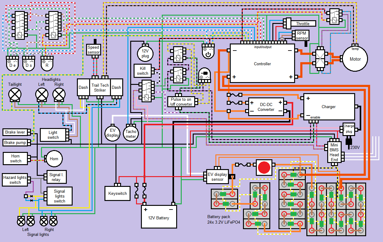
Blog / Drawings
Posted on 13 June 2014 at 01:06 am (CET)
Posted on 13 June 2014 at 01:06 am (CET)
Past few days I've been busy drawing the whole wiring diagram. I'm pretty sure everything will actually be connected like this now. Only those 3 wires of the Battery Management System I'm not really sure about how to connect them yet. These are for drastically reducing the power when the batteries are empty so you can't undercharge them. But there should still be enough power to get the quad bike off the road safely. This can be connected in a few ways so I'll still wait with this.
Also made 2 extra circuits in it with a few buttons and relays. The one on the top left is for switching between low power (Drive Eco), high power (Drive Sport) and Reverse. And the one in the middle is for starting and stopping the charge process when the charge plug is connected. I might still get an actuator for this so the charge plug will get locked with this circuit while charging.
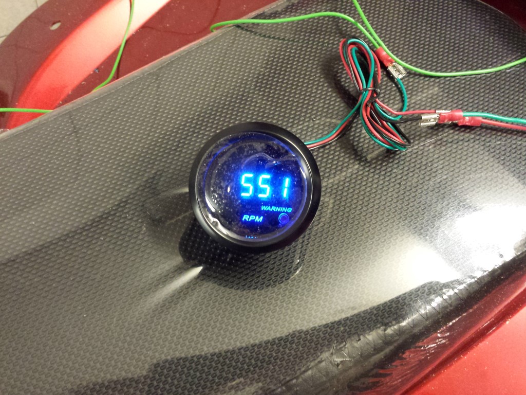
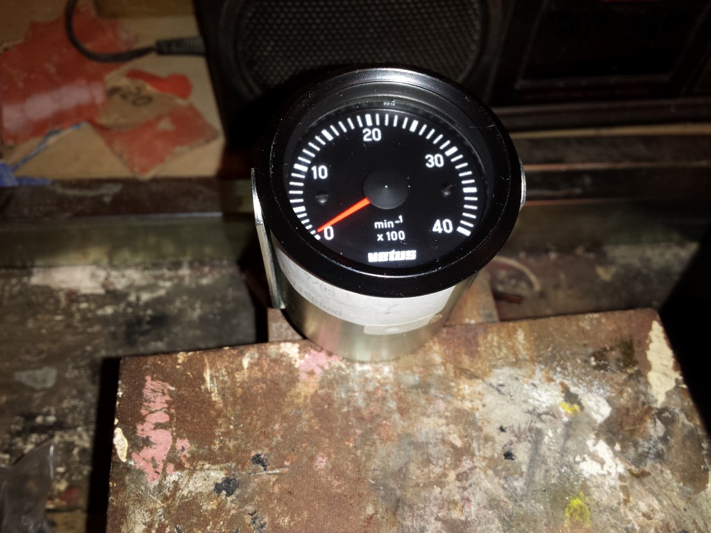
Also have another new tachometer, this time one from Hong Kong for 10 euros. And third time's the charm, this one works perfectly.
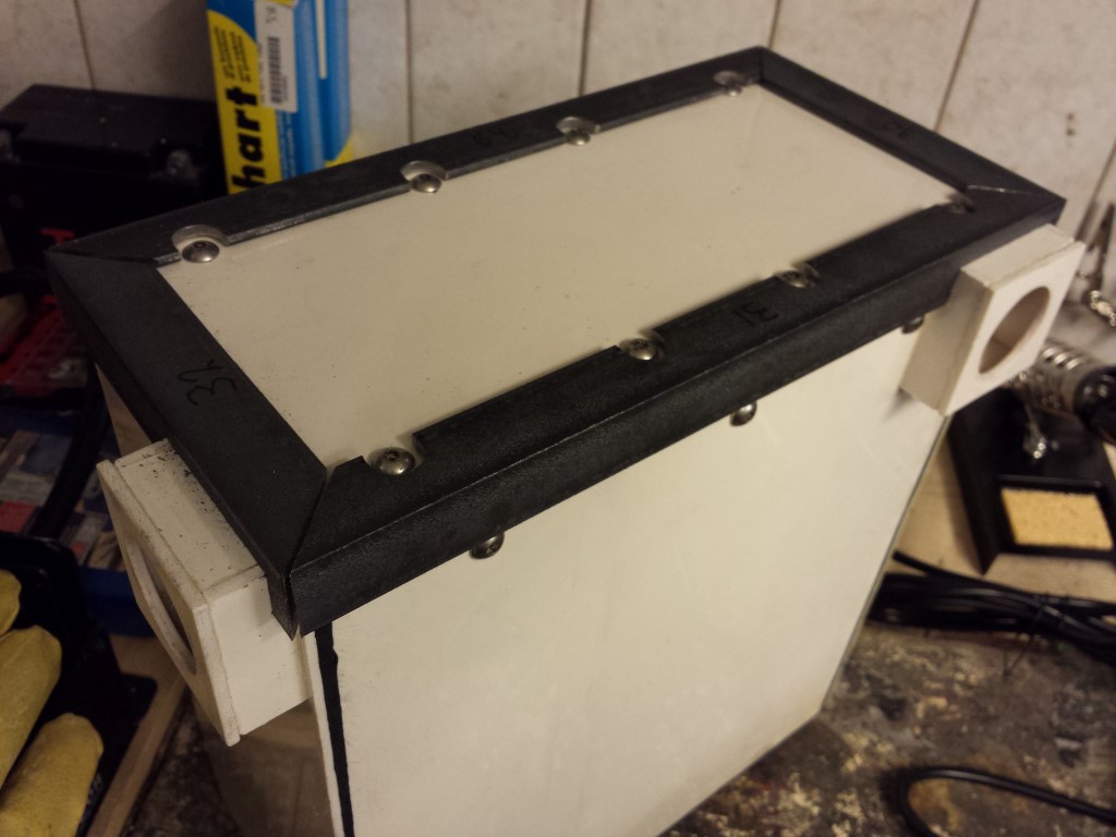
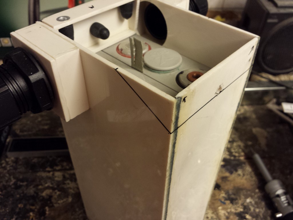
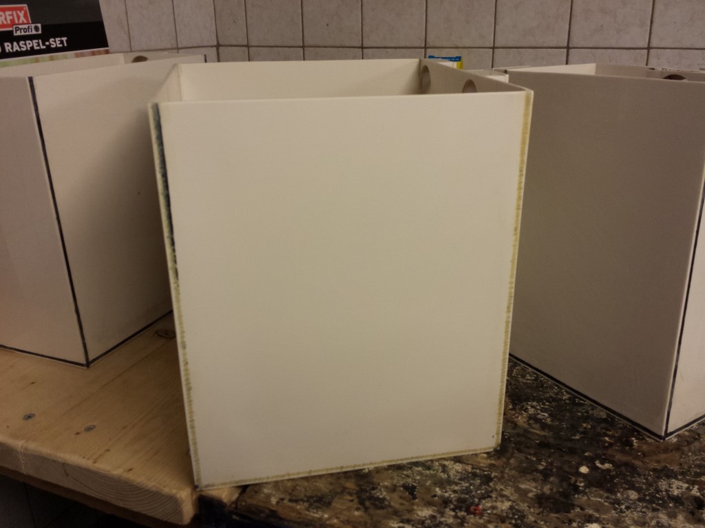
For the rest I've still been busy with the corner profiles on the side of the covers. Have to make quite a lot of cutouts in them for the cable glands and bolts. So this'll still take me a while. But for this battery box they're all done, still 3 to go.
Posted on 22 May 2014 at 10:46 pm (CET)
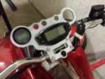
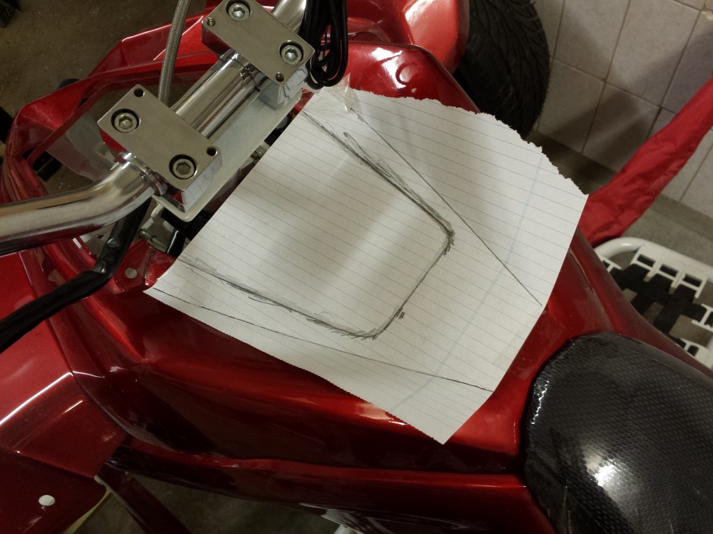
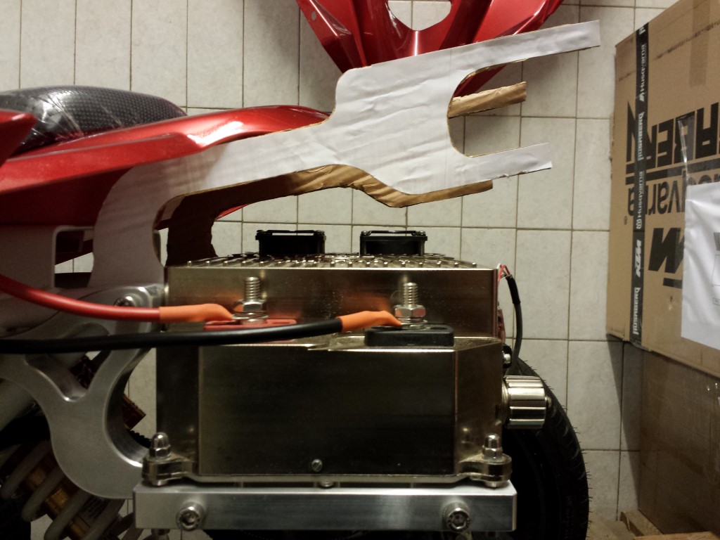
I've made some drawings again. These will probably be the last 2 aluminium parts that still have to be made. First is a mounting plate for all the gauges and switches. This will be mounted on the handlebar.
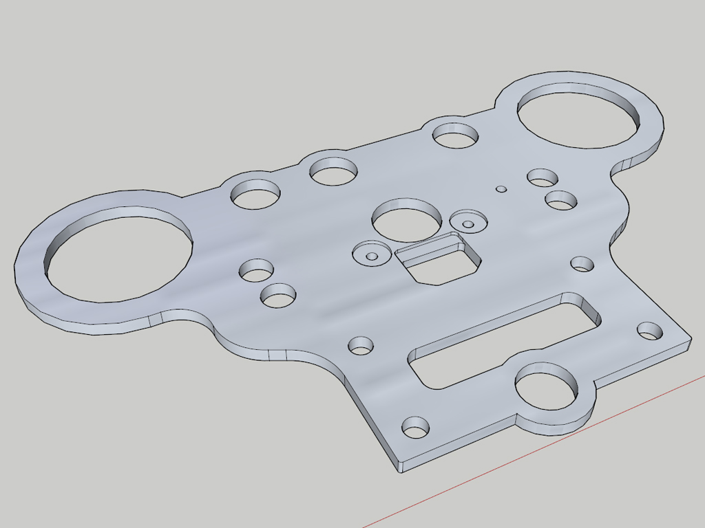
As usual I made a paper model of it to see how everything would fit.

It all fits pretty good, just the angle of the gauges isn't really that great. Would be better if the plate could be bent to an angle of about 20 degrees, would be looking straight at the gauges then when sitting on the quad bike. I modified the drawing a bit to make this possible. Also made some small changes to make it easier to route and added another hole for the hazard lights switch. The plate will be bent by about 20 degrees on that line in the middle.
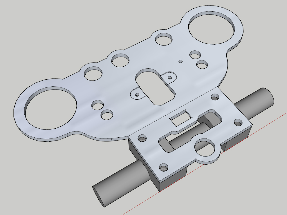
To be able to measure a few more things I had to place the fenders again. So here's a nice picture of the whole quad bike. It's actually starting to look like something.
I just ran into a problem with the battery box that's in the front below the carbon fender. It barely doesn't fit and the box is being pushed against the steering shaft which isn't a good thing. So I'll have to modify this box a bit, make it beveled on one side. Because of this I also haven't been able to saw the steel corner profiles to size yet since they'll have to be different for this box as well.
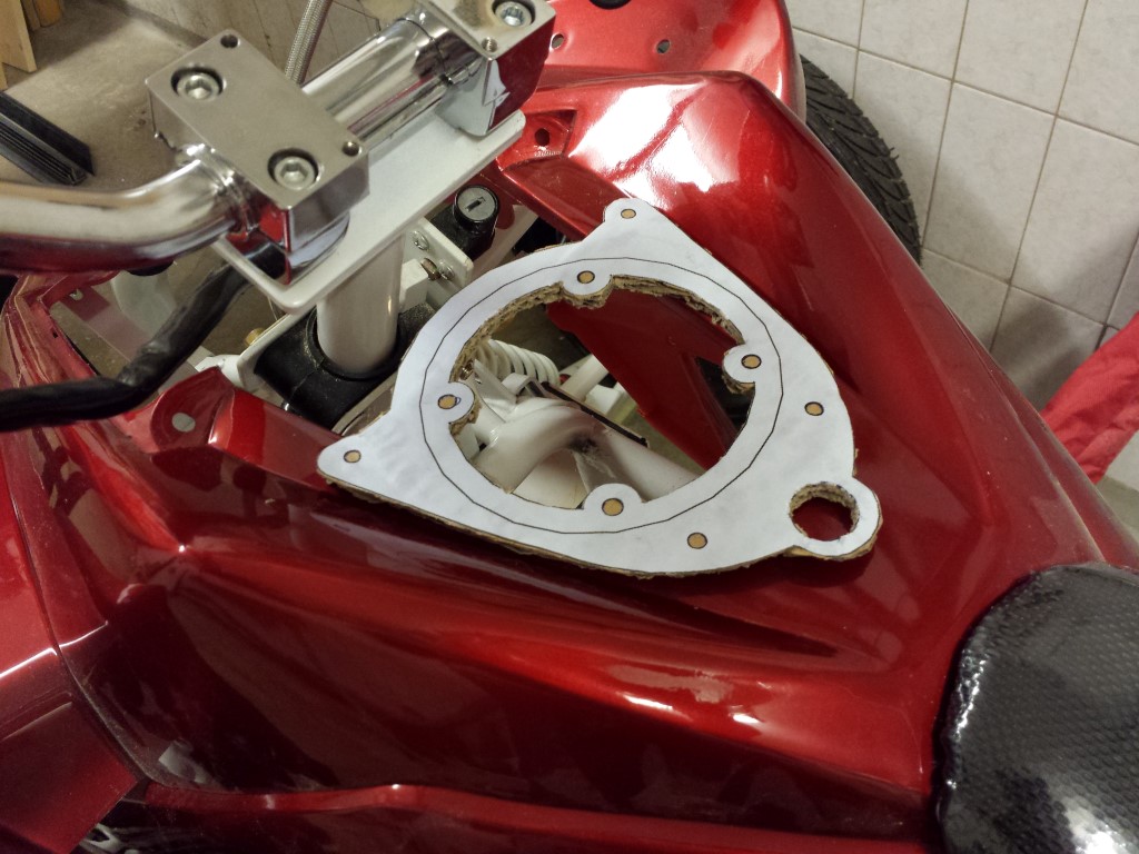
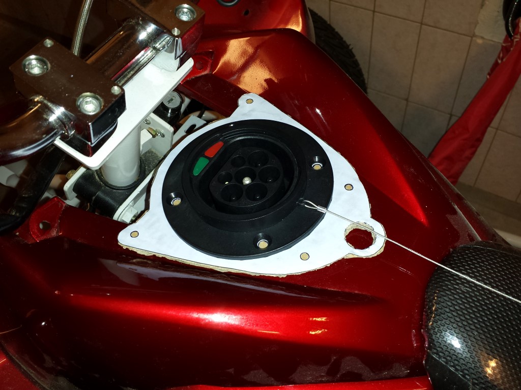
Then there's still the other plate. This one's for the charge inlet and will be in the same spot where the gas filler cap once used to be. For this I needed all the sizes of the fender which is quite tricky since the lines aren't straight but bent just slightly. I had the idea of just sticking a piece of paper on it and then try to find the lines with a pencil, worked pretty well.
Now I could easily measure everything while drawing without having to take the whole fender with me.
I again made a paper model of it and it all fits perfectly, no modifications needed.
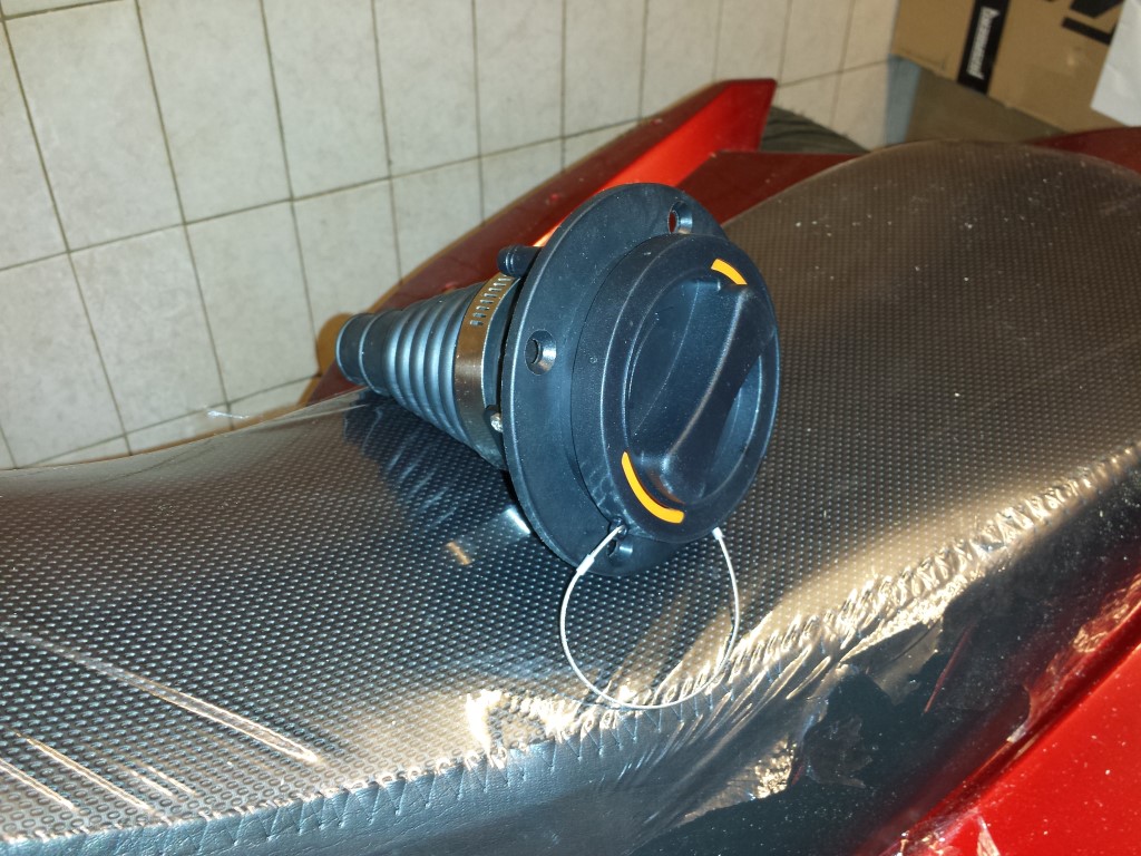
The charge inlet is new after some advice from Rebbl, this is a mode 3 type 2 (IEC 62196). It's the standard everywhere in Europe now for all electric vehicles. Last year or so I already bought a CEE inlet but meanwhile this won't be approved anymore at the RDW (our institute for road safety). So unfortunately I had no choice but to buy this one. But I'm quite happy with it now, it's much more solid, safer and also waterproof.
Also bought a new analog tachometer for a very cheap price. But unfortunately I can't get this one to work either. I was really sure it would work with this one since it normally gets connected to the alternator and also gets a pulse signal. But it doesn't do anything with the pulse signal that's coming from the controller. So I'll have to look for a solution again.
Posted on 3 May 2014 at 12:26 am (CET)
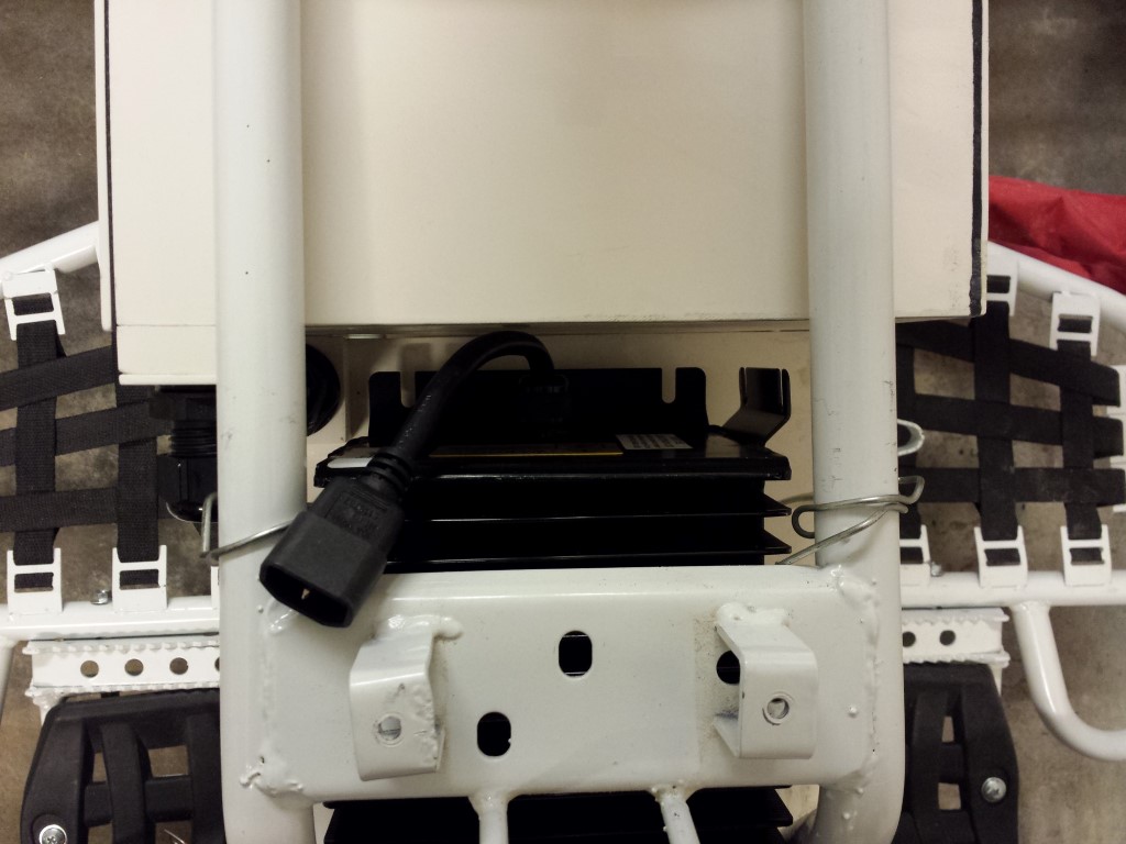
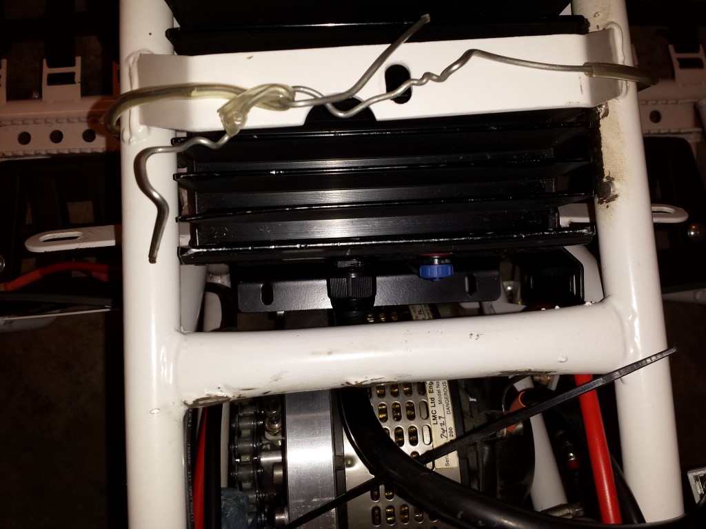
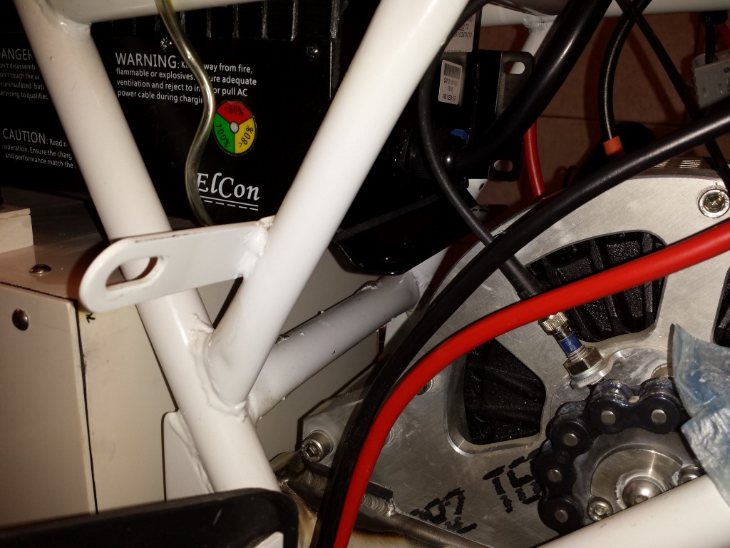
Besides the battery boxes there's still something else that has to be attached to the frame, the charger. Today I checked how it would fit and what I'll have to make for this. Thought I'd show how it'll be placed, don't think I've showed this yet.

It'll be placed as high as possible so I can still easily get the large battery box in and out without having to remove the nerfbar, pedals and heel guards. But I won't bother thinking too much about how to attach this. There are already 4 mounting points on there (also 2 on one side but I'll have to cut these off since they're in the way). On the front I can just weld a thick steel plate at the top between the tubes and place 2 long studs down there. On the rear I can weld 2 mounting points on that tube in the middle and bend the mounting points on the charger itself straight down. Will be firmly attached like that I think.
And the idea I have for the battery boxes is just some corner profiles of 3 mm thick steel welded together with some mounting points on there. There'll also be mounting points on the frame itself and they'll be firmly attached like that. I'm not really sure yet if it'll actually be like this but I think it will.
Posted on 8 April 2014 at 06:47 pm (CET)
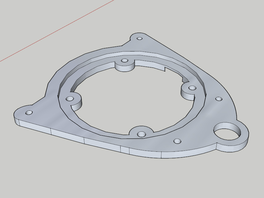
I completed the drawing of the mounts for the top case and rear lights. Also made a paper model of it again to see if it fits. It barely fits as it should.
First here's the drawing of how it'll be like. Ofcourse the real ones will look a little better with skewed edges and again an opening in the bigger part. The top 2 mounts are ofcourse for the top case, the bottom one is for the rear lights.

They just come out from under the fenders. I wanted as much clearance as possible between the mounts and the controller so it'll stay visible well. The top case will also be as low as possible and will be a bit tilted (about the same as the fenders), will look better than completely straight I think. Same for the lights, by default these are a bit tilted as well so I wanted to keep this about the same. It'll only be a little lower.
But it'll be easier to see once they're made. First I have to discuss with the metalworking company if it can all be done and if it's not too expensive. Will probably take a while before it's done I think, depends how busy they are.
Posted on 7 September 2013 at 12:30 am (CET)
Made some progress again.
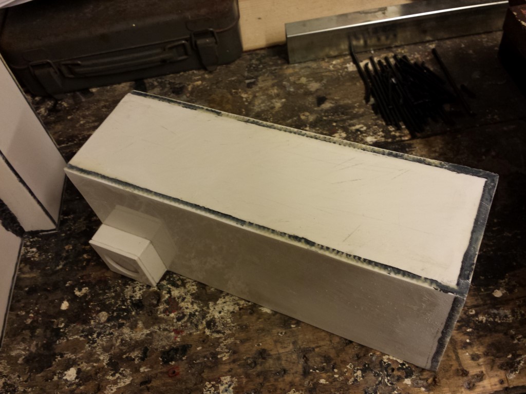
These past few days I've been busy with epoxy glue on the battery boxes. Works pretty well, is very strong and fills reasonably good. Just not everywhere since the grooves are rather deep in some places. But might be able to just use filler for that before it gets sprayed. In any case it's sturdy enough now.
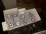
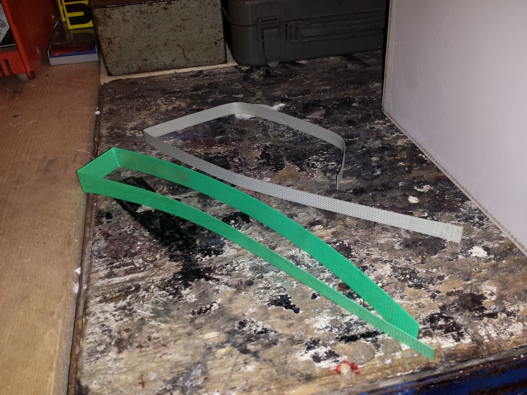
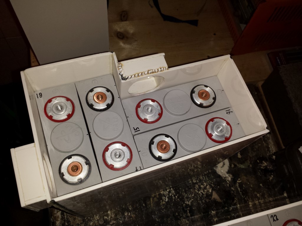
Today I tried fitting the batteries in all the battery boxes again. I got some green plastic straps from someone of the China Quad forum during a club meeting but unfortunately these were just a bit too thick (0,9 mm). But coincidentally I received a package today with some smaller gray plastic straps around them (0,65 mm). It were 2 straps with just the right length to make 4 pieces out of them.
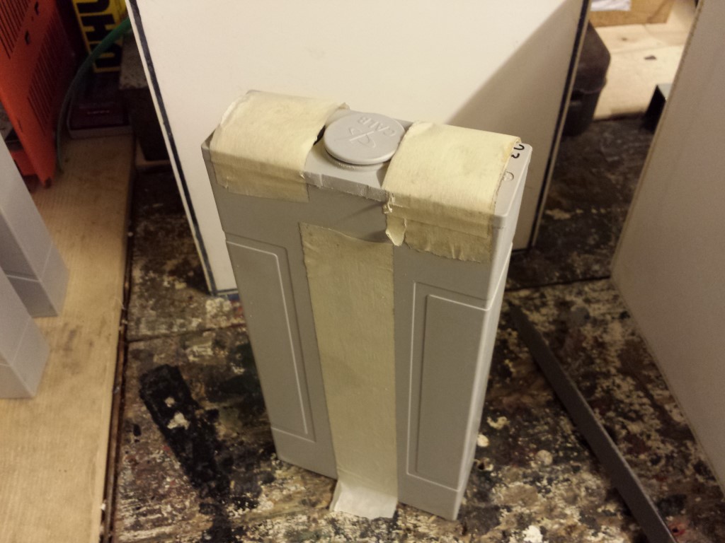
In the biggest and smallest battery box they fit perfectly without having to modify anything. In the bigger one which has 6 batteries I had to file the top of one of the batteries a bit. The plastic enclosure is thick enough anyway and the top part kind of sticks out a bit on them all. Ofcourse I first put some tape on the terminals. Accidentally causing a short circuit with the file doesn't seem fun to me. But it worked, the strap fits in this battery box as well now, can still get the battery out with a little force.
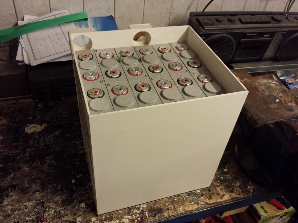
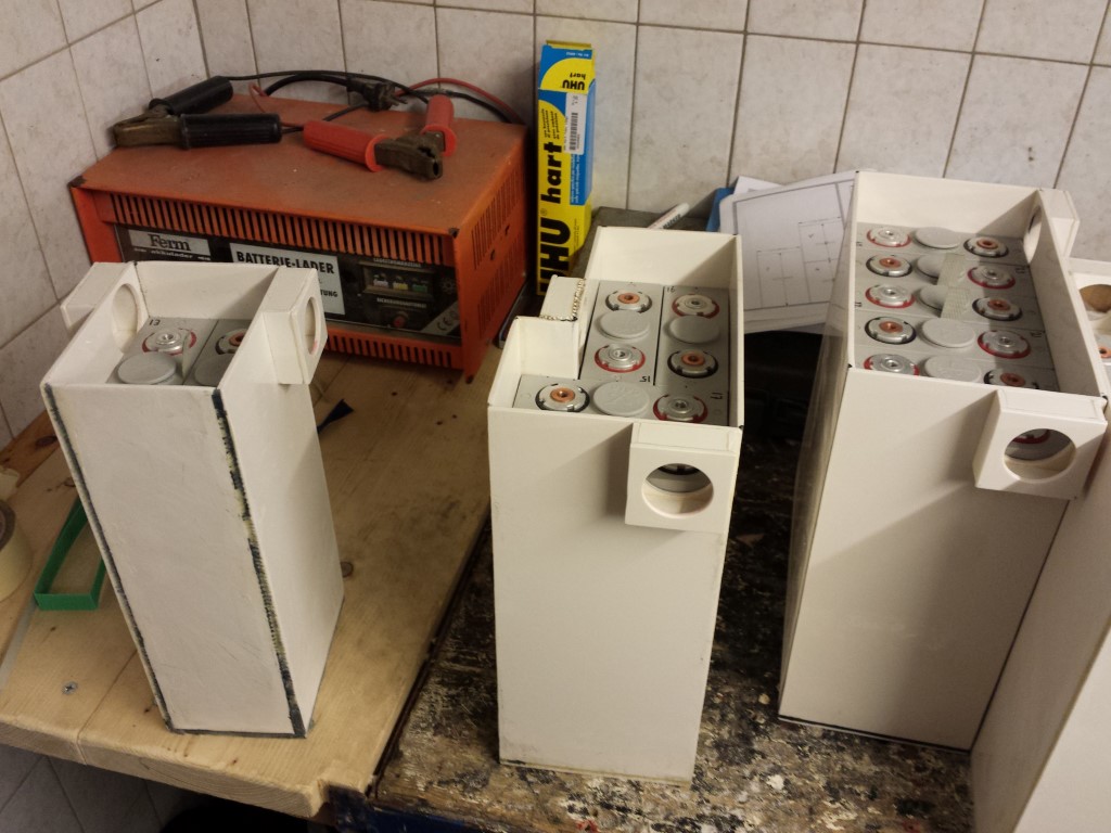
But then the battery box with the corner in it. Been messing around with this box since the beginning and ofcourse it gave me some more problems now. Without a strap the batteries barely fit. There just wasn't enough space for a strap so I also filed the top of the batteries quite a bit. But unfortunately the problem isn't at the top but at the bottom of the battery box. There's just no space left there at all for a strap and I can't file the bottom of the batteries. So I have no idea what to do with this. For now I just left them in without a strap. Can still get them out by placing the battery box upside down but ofcourse this won't work once it's fitted onto the quad bike. I will try and find a solution for this later.
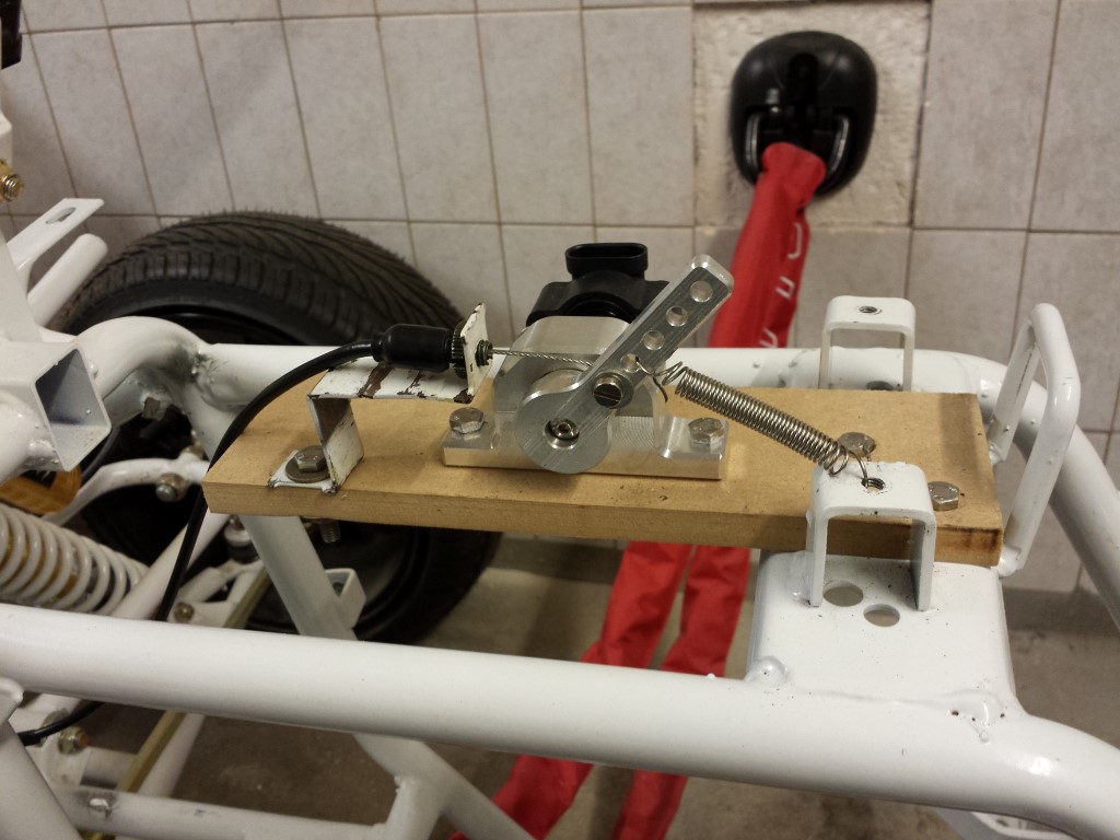
For the rest I also temporarily fitted the hall sensor and placed the throttle cable on it. This is only for the testride which will be soon, eventually I'll make something different for this and also in an enclosure so there can't get any dirt or water in there.
Now I just need to wait for the controller mounts, if all goes well they should be done wednesday and then I can finally attach the controller to the frame.
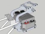
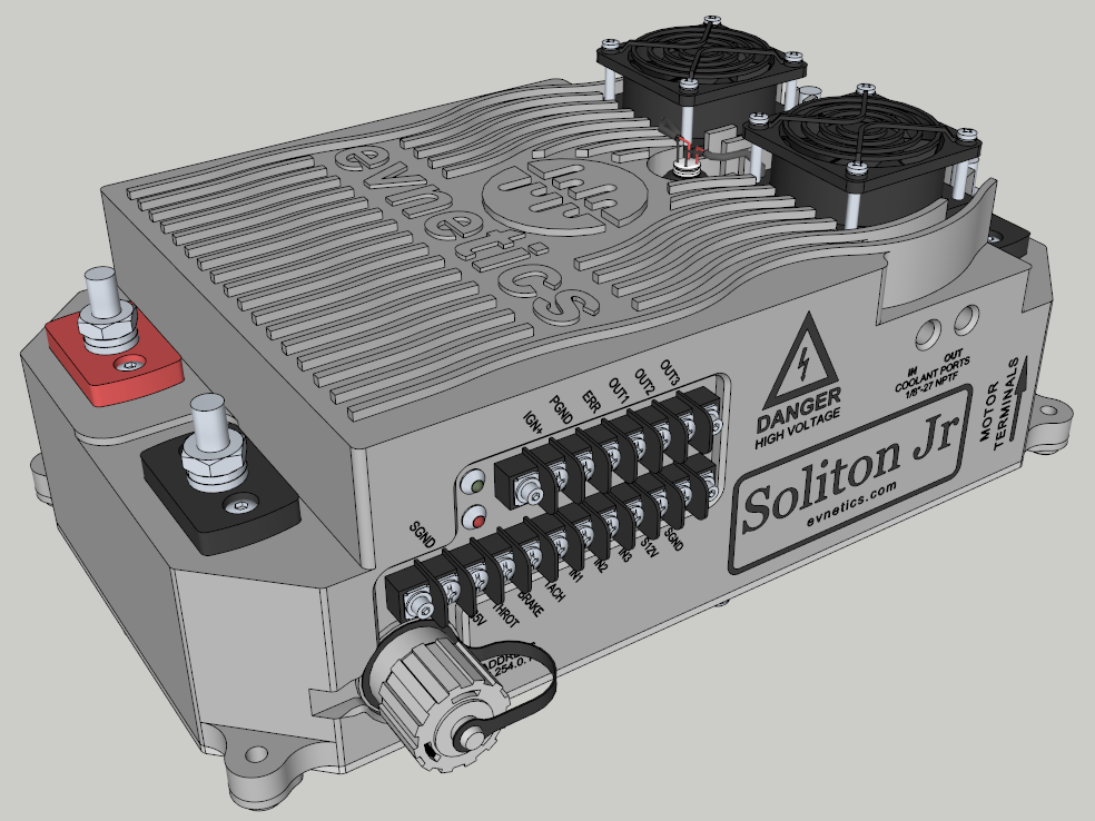
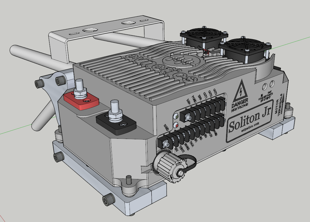
Was a bit bored meanwhile so I tried to replicate the controller in SketchUp. Think it turned out pretty good. I just can't get it to shine so it's very gray now.
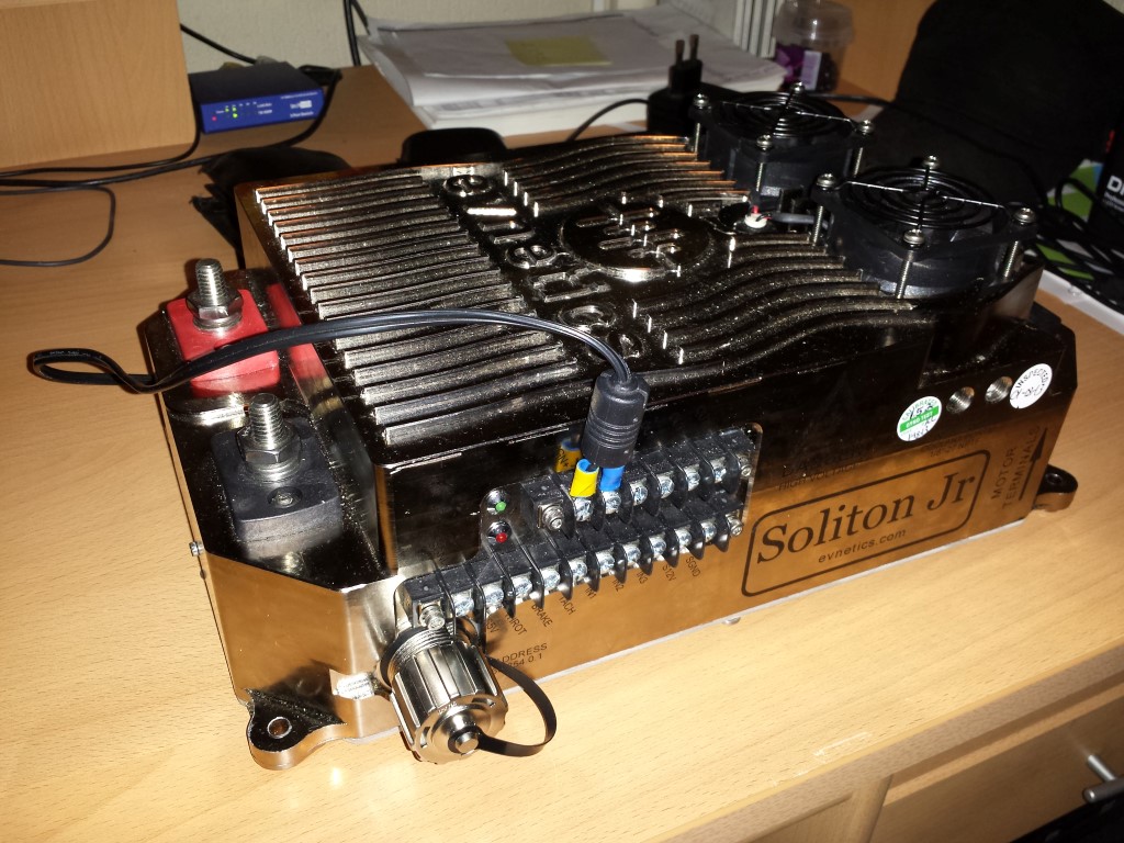
And here on the mounts. Hopefully it actually fits this well.
That was it for today.